New Nursery Air Conditioning, East Barnet EN4
Air conditioning for a new nursery in East Barnet EN4: one Samsung system heating and cooling fifteen rooms, photographed from bare pipework to cassettes in the ceilings.
- BuildingA new nursery, under construction
- PhotographedOctober 2026
- Postcode areaEN4
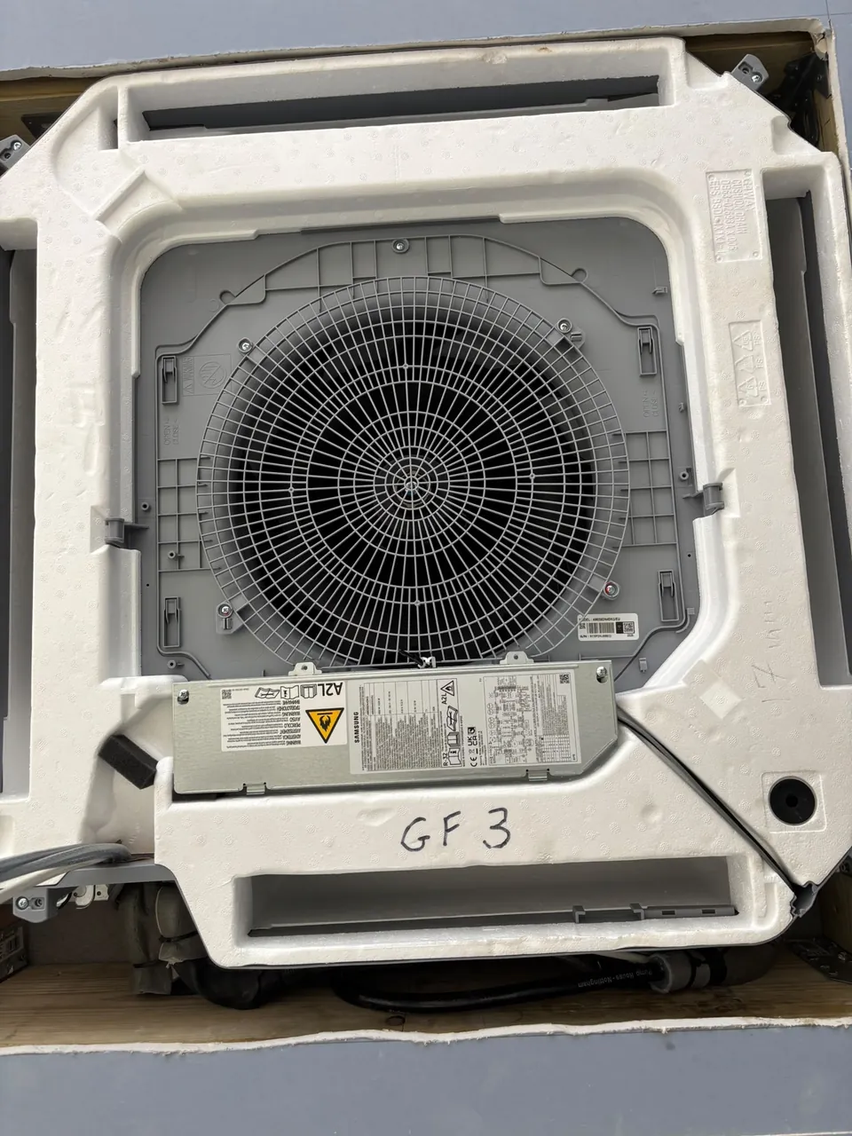
Samsung VRF air conditioning in a new nursery, East Barnet EN4
We are installing the air conditioning in a new nursery being built in East Barnet EN4. It is one Samsung VRF system on R-32 serving fifteen rooms: six on the ground floor, six on the first floor and three on the top floor.
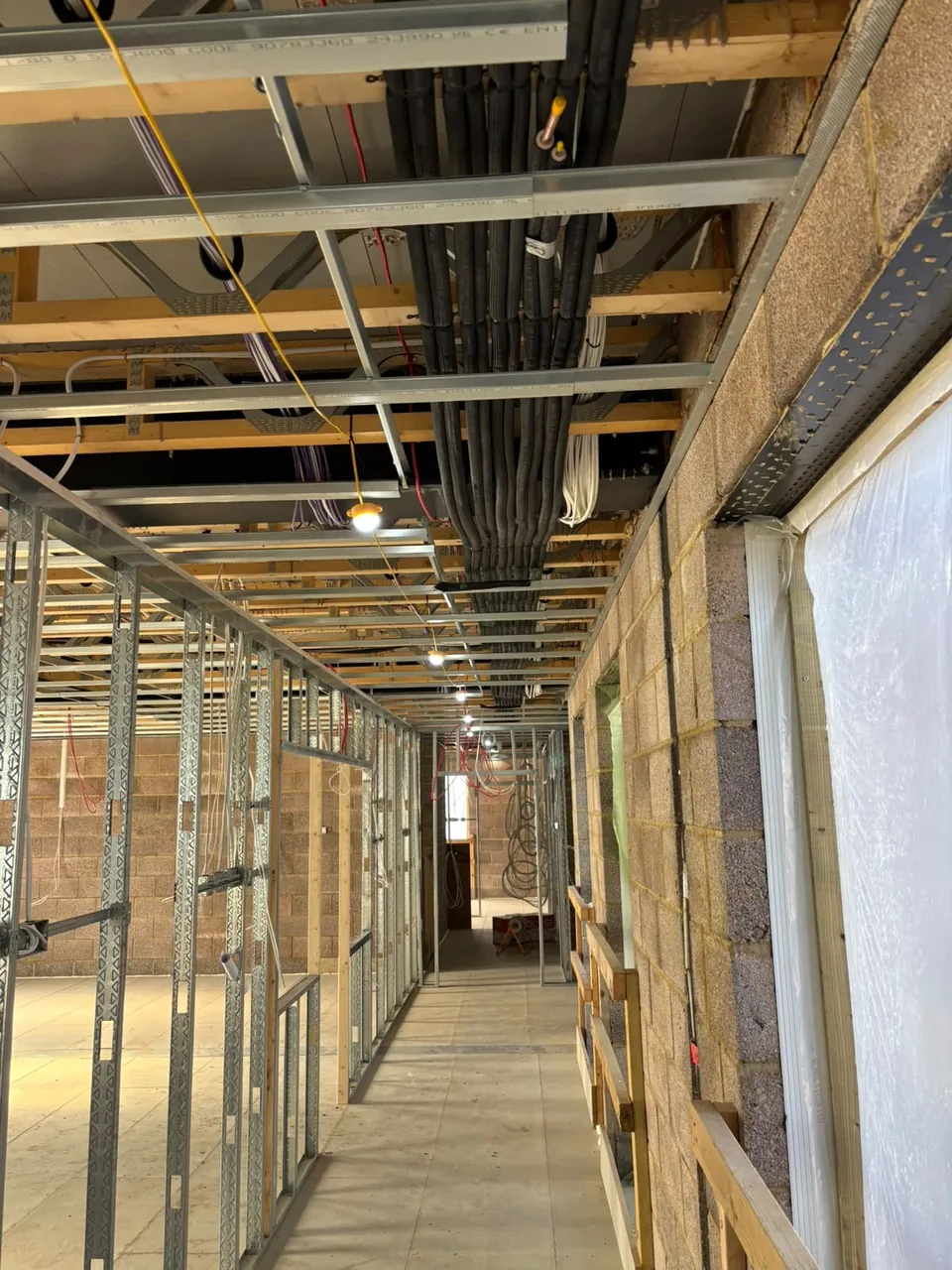
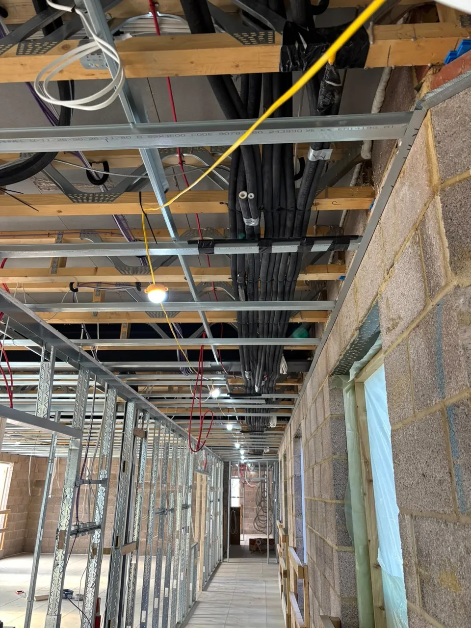
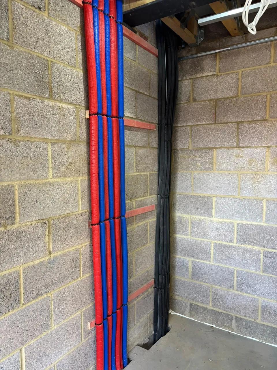
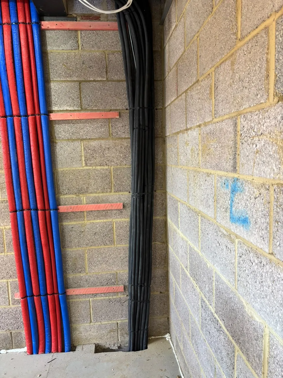
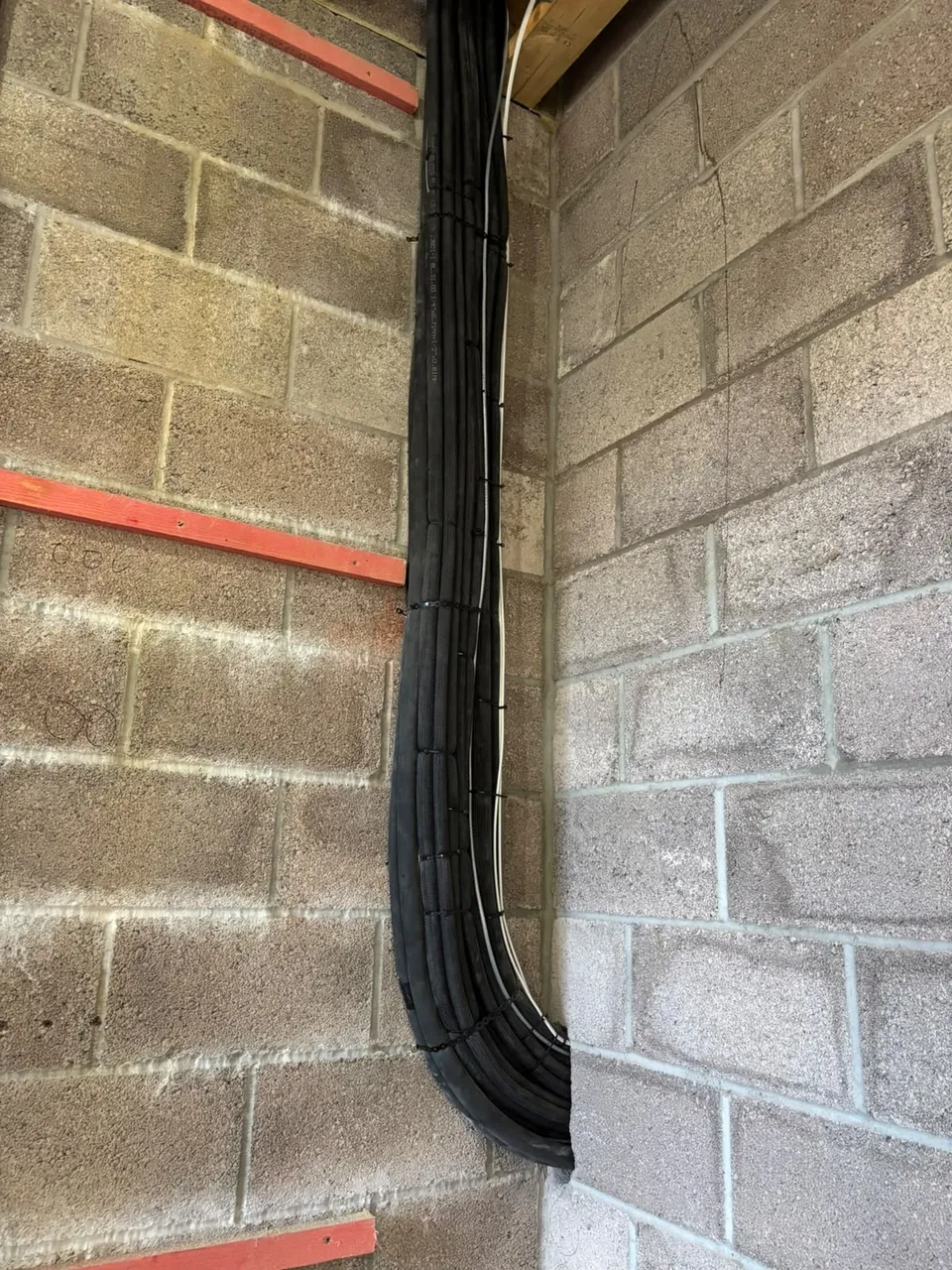
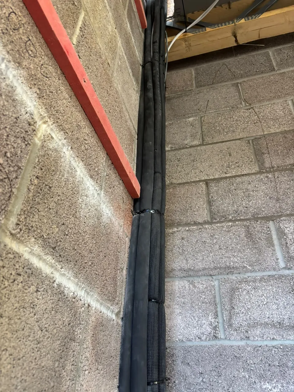
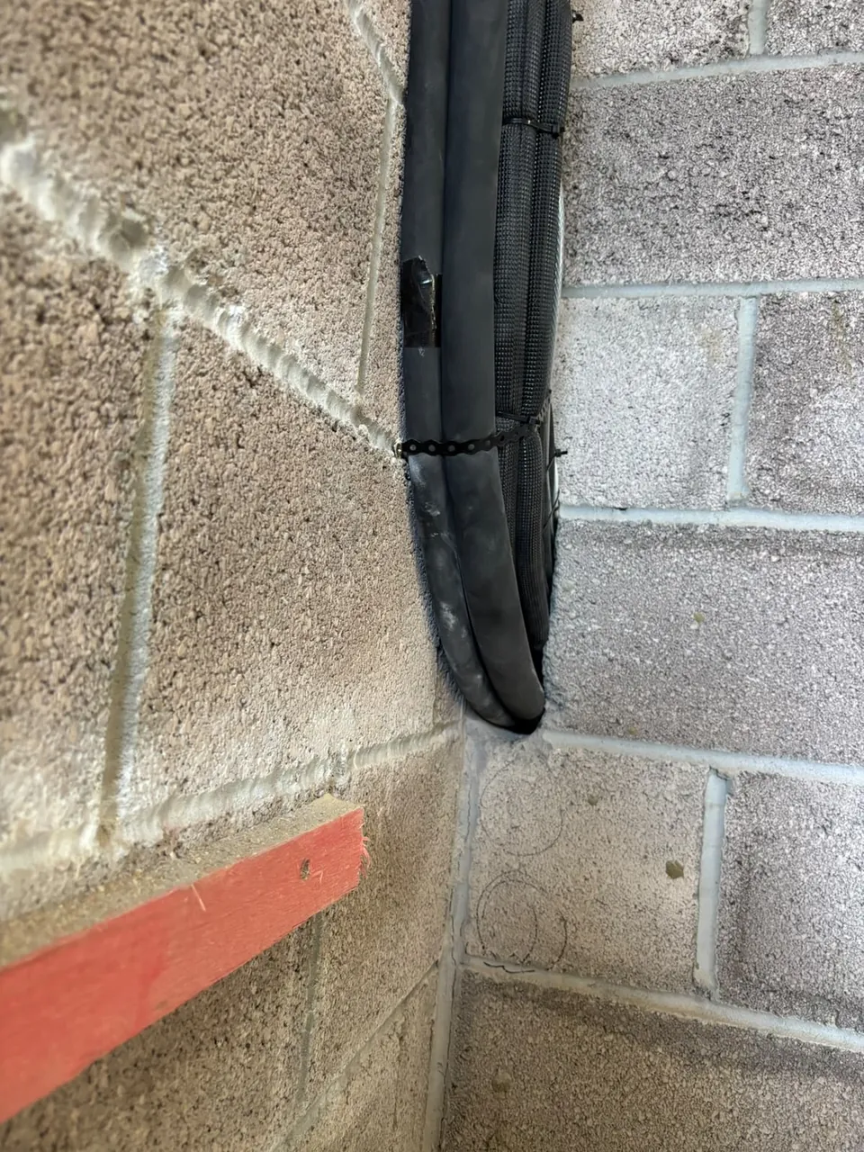
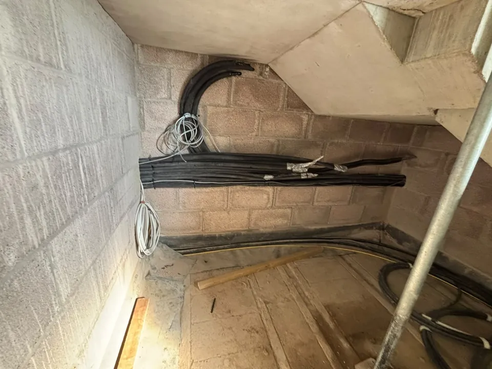
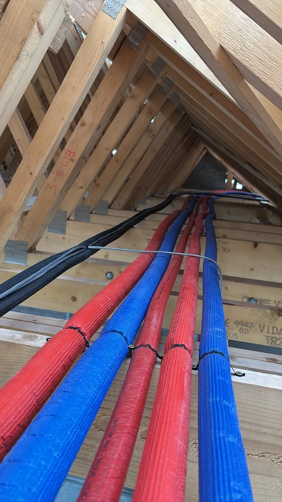
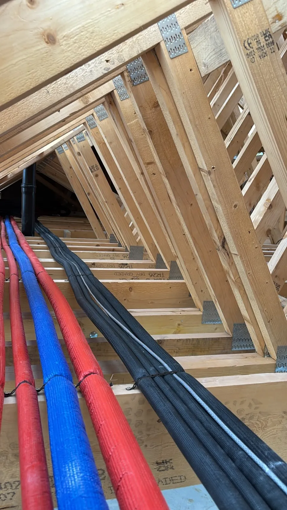
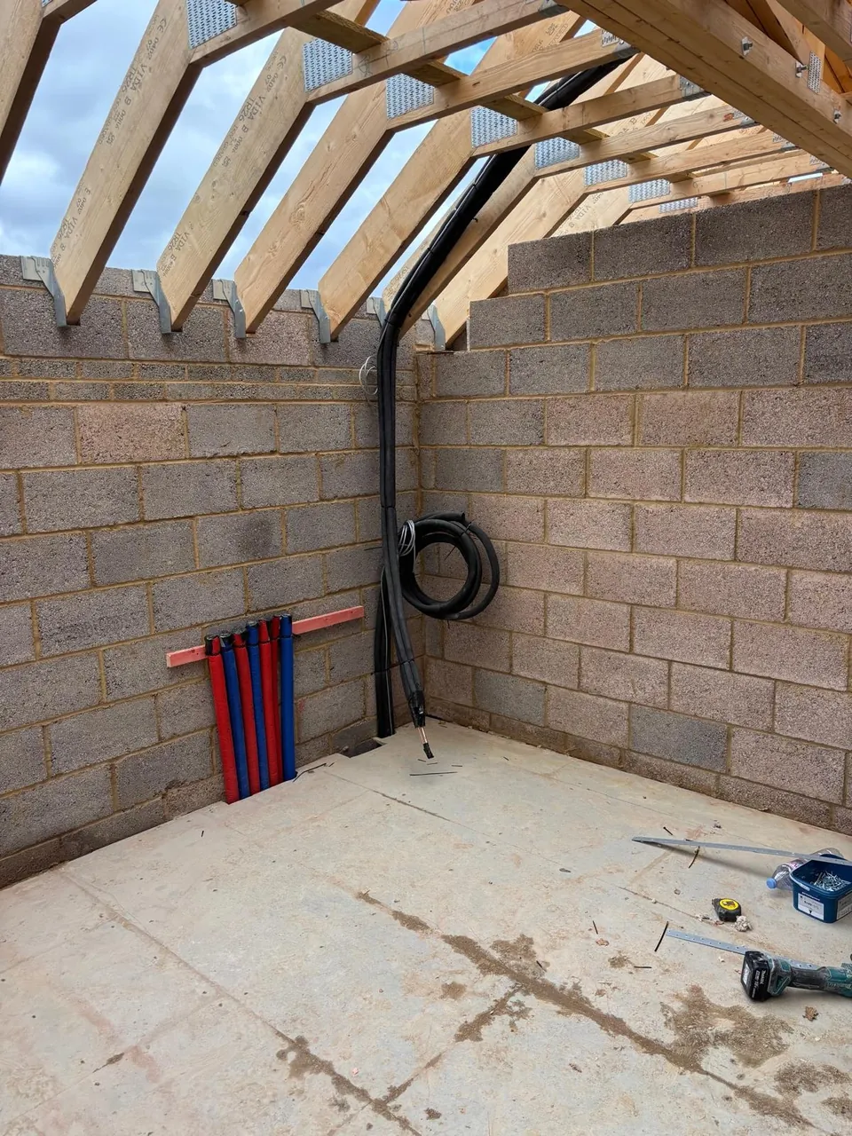
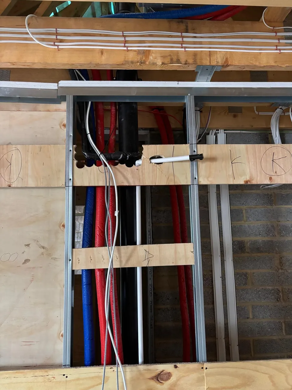
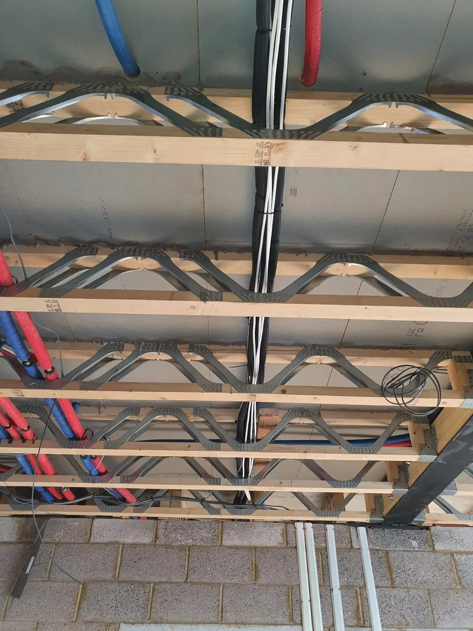
The first photographs below are the first fix, taken while the building was still a shell: insulated refrigerant pipework and control cables run through the ceiling void above the corridor, down a riser between floors and across the roof space to every unit position.
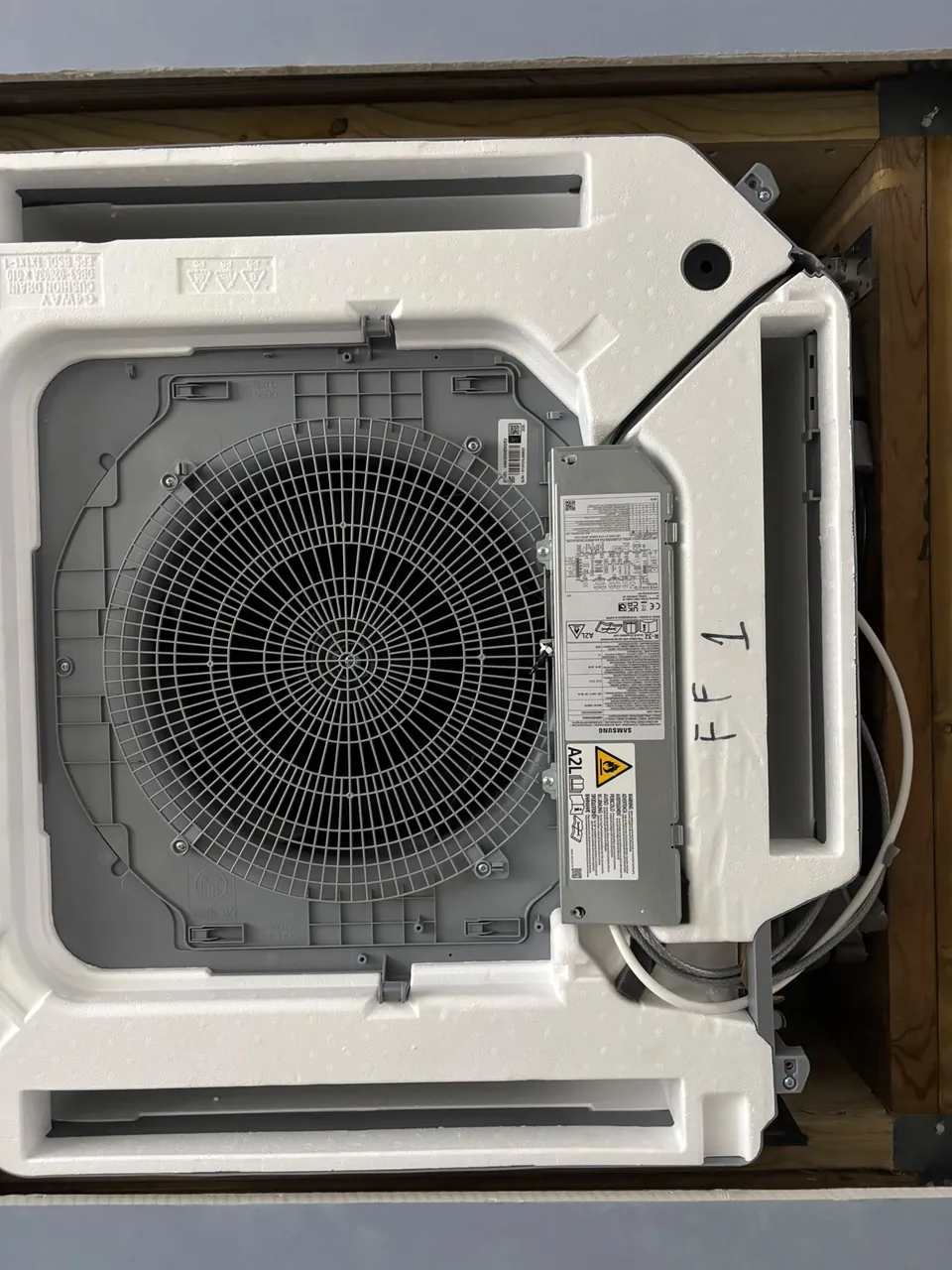
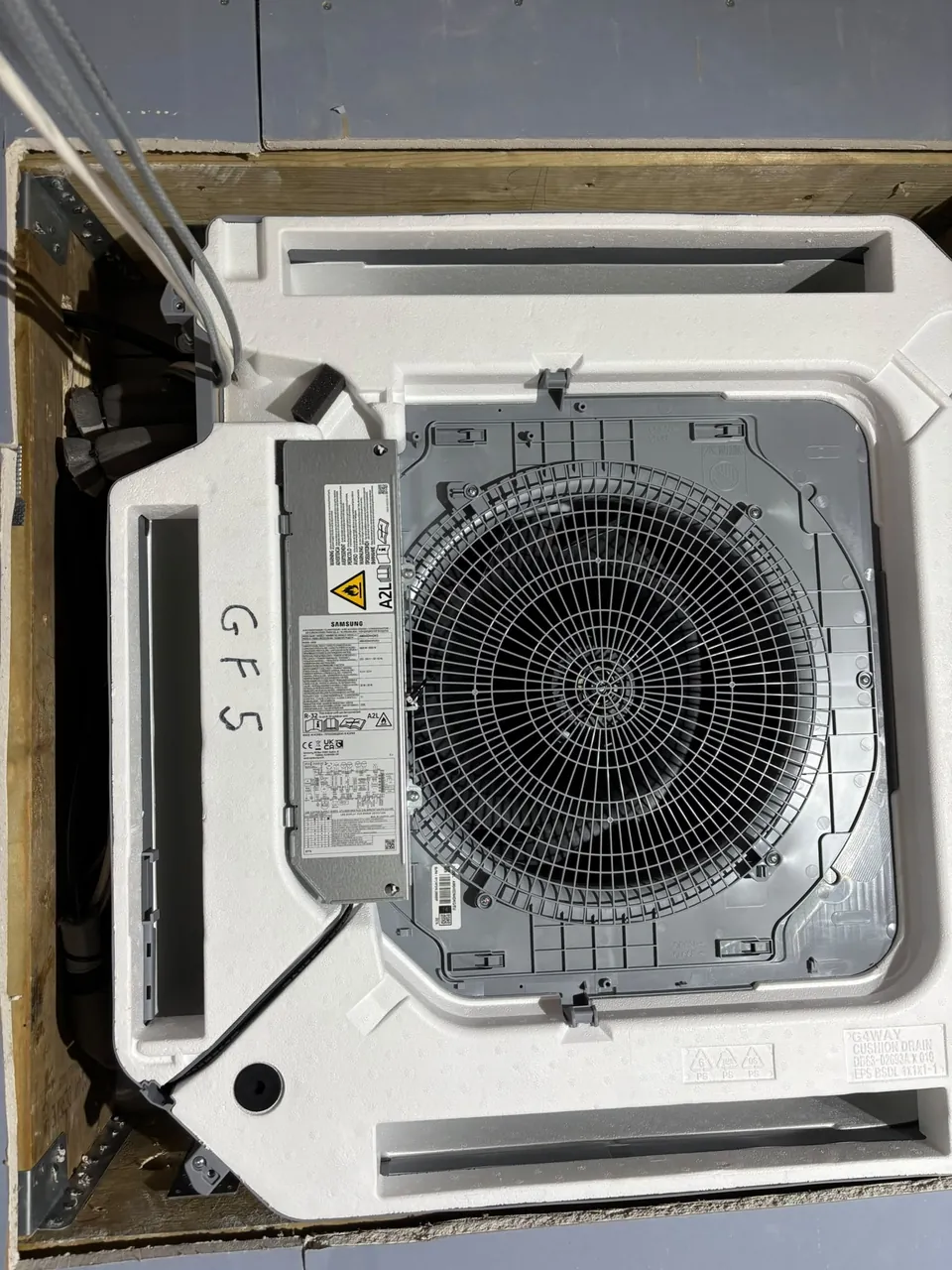
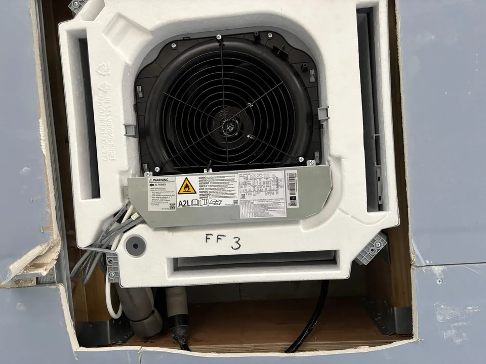
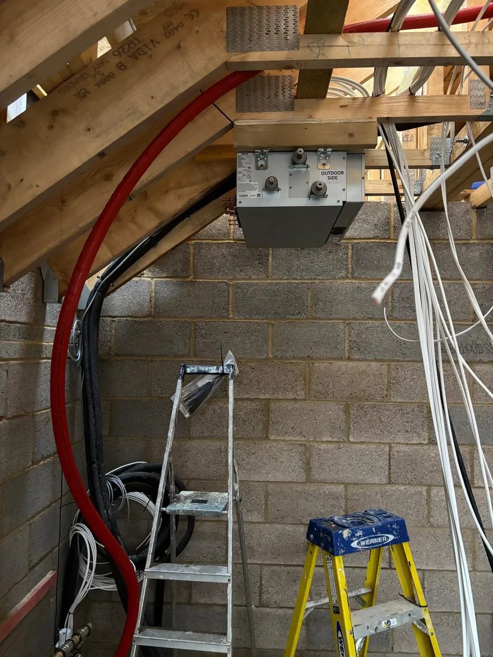
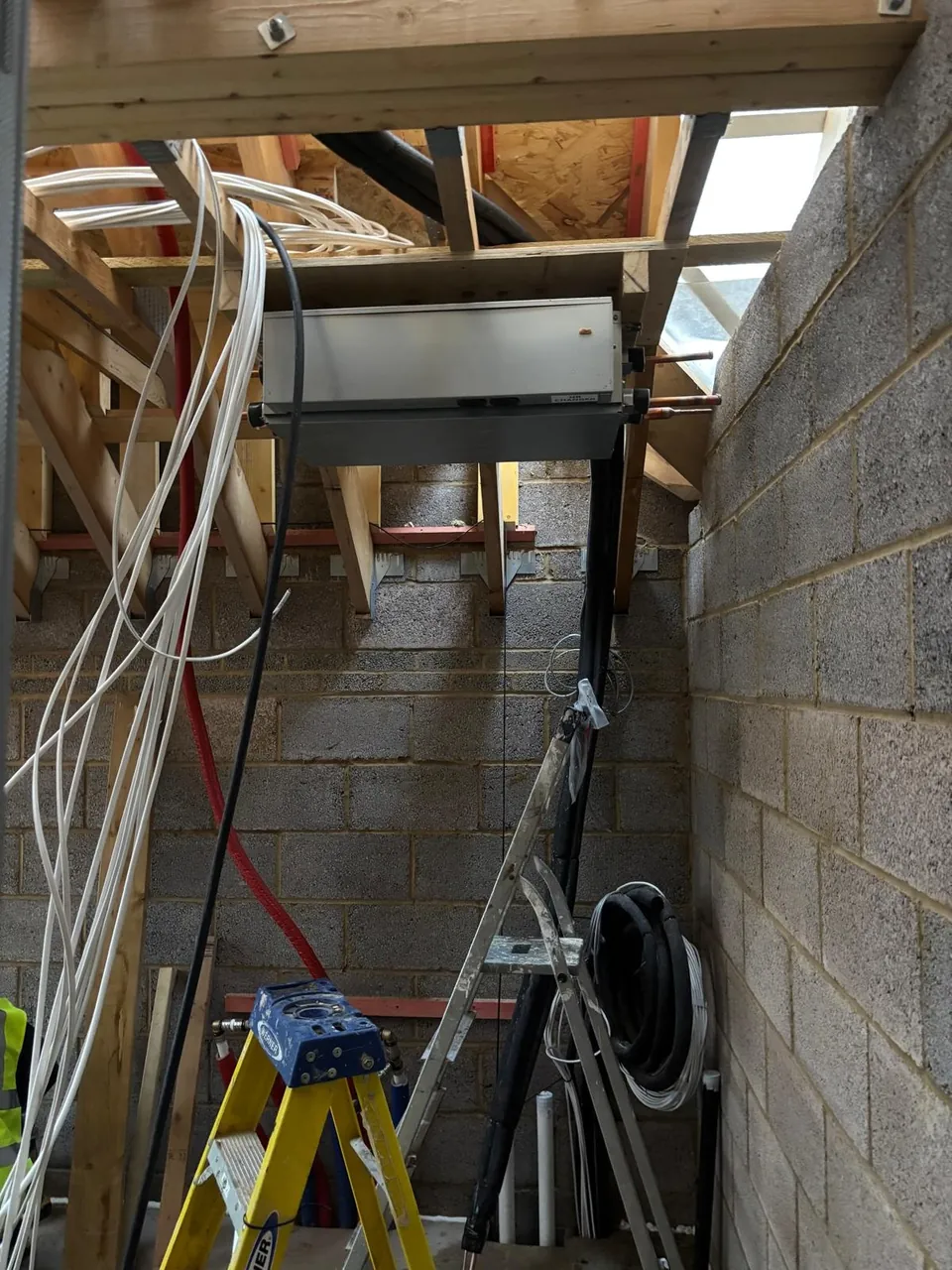
The later photographs, taken on 25 October 2026, are the second fix. The twelve ceiling cassettes on the ground and first floors are hung in the ceiling grid, and the three mode change units that let each room heat or cool on its own are fixed and piped in. The grilles go on once the ceilings are finished, and then the system is commissioned.
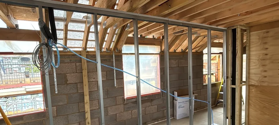
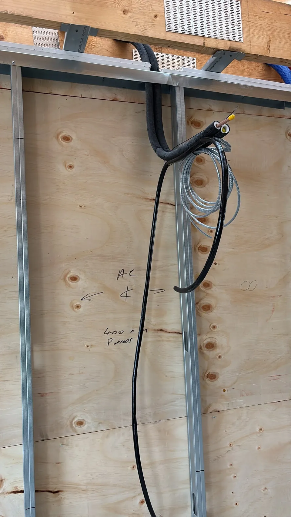
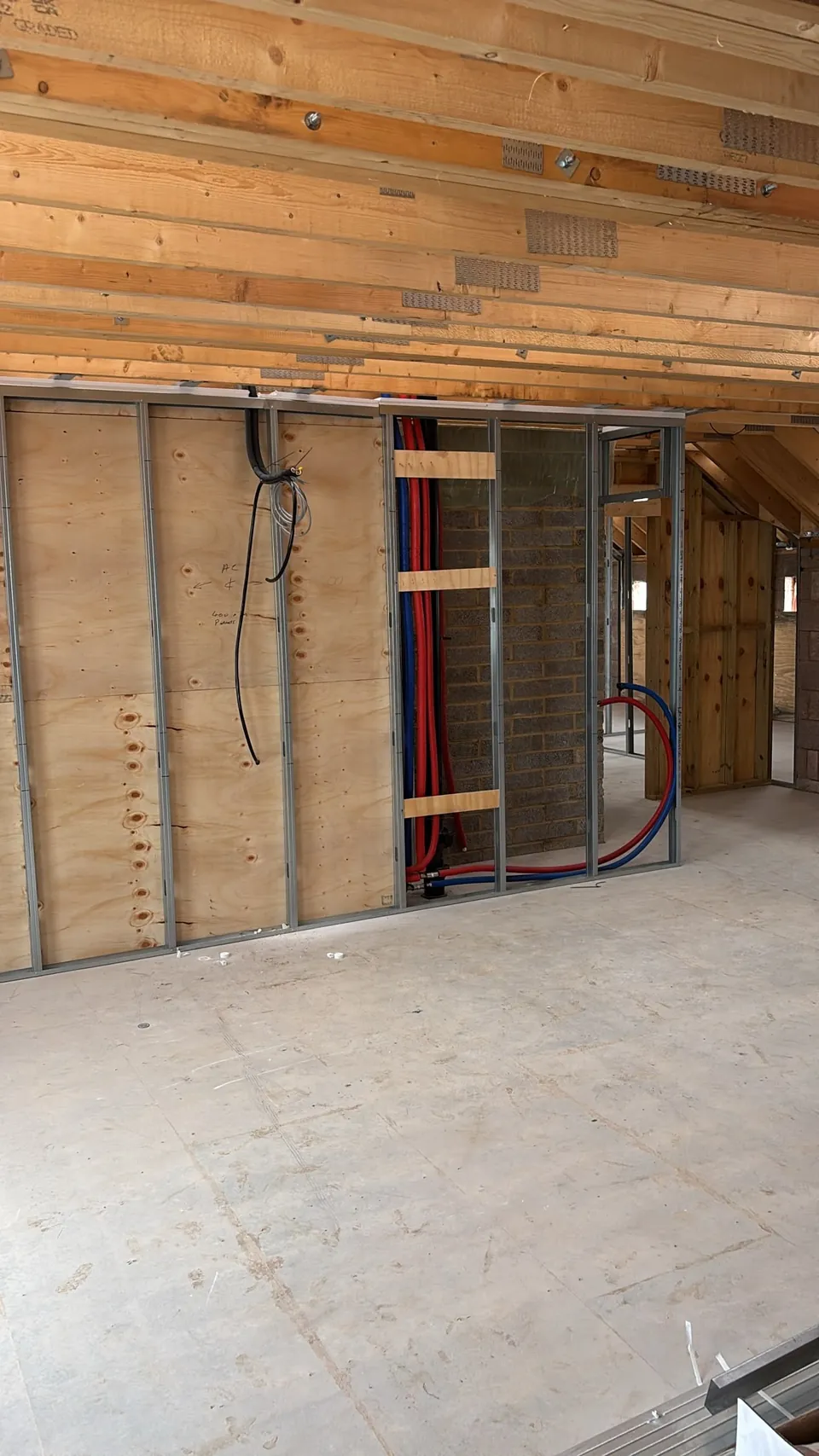
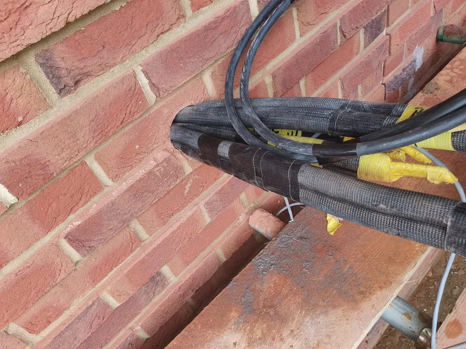
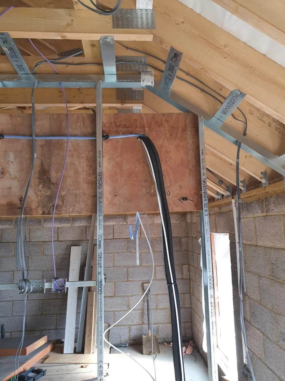
The last three photographs, from the end of October 2026, show where the pipework goes next. On the top floor, under the open roof, the lines come down the stud walls to plywood boards fixed at each unit position, ready for the units to be hung. Outside, the insulated bundle leaves the building through the brick wall at the eaves, on its way to the outdoor units. This page will be updated again with the finished photographs.
The job in short
- Where: East Barnet EN4, north London
- Building: A new nursery, under construction
- System: Samsung VRF with heat recovery, R-32
- Indoor units: Fifteen: six on the ground floor, six on the first floor, three on the top floor
- Sizes: From 1.5 kW in the smallest room to 9.3 kW in the largest
- Stage shown: First fix pipework, then cassettes and mode change units in place, then the top floor and the route outside
- Still to come: Cassette grilles once the ceilings are finished, then commissioning
- Photographed: October 2026
Photos from the job
Planning air conditioning for a building?
New build or existing, tell us what the building is and what stage it is at. We design from a heat load calculation and send a fixed written price. No cost and no obligation.
Page updated